Final Project for Embedded Systems Course at Tel Aviv University
Pavel Anissimov & Evgeny Fraimovitcvh
Winter Semester 2010/2011
Course lecturer: Sivan Toledo
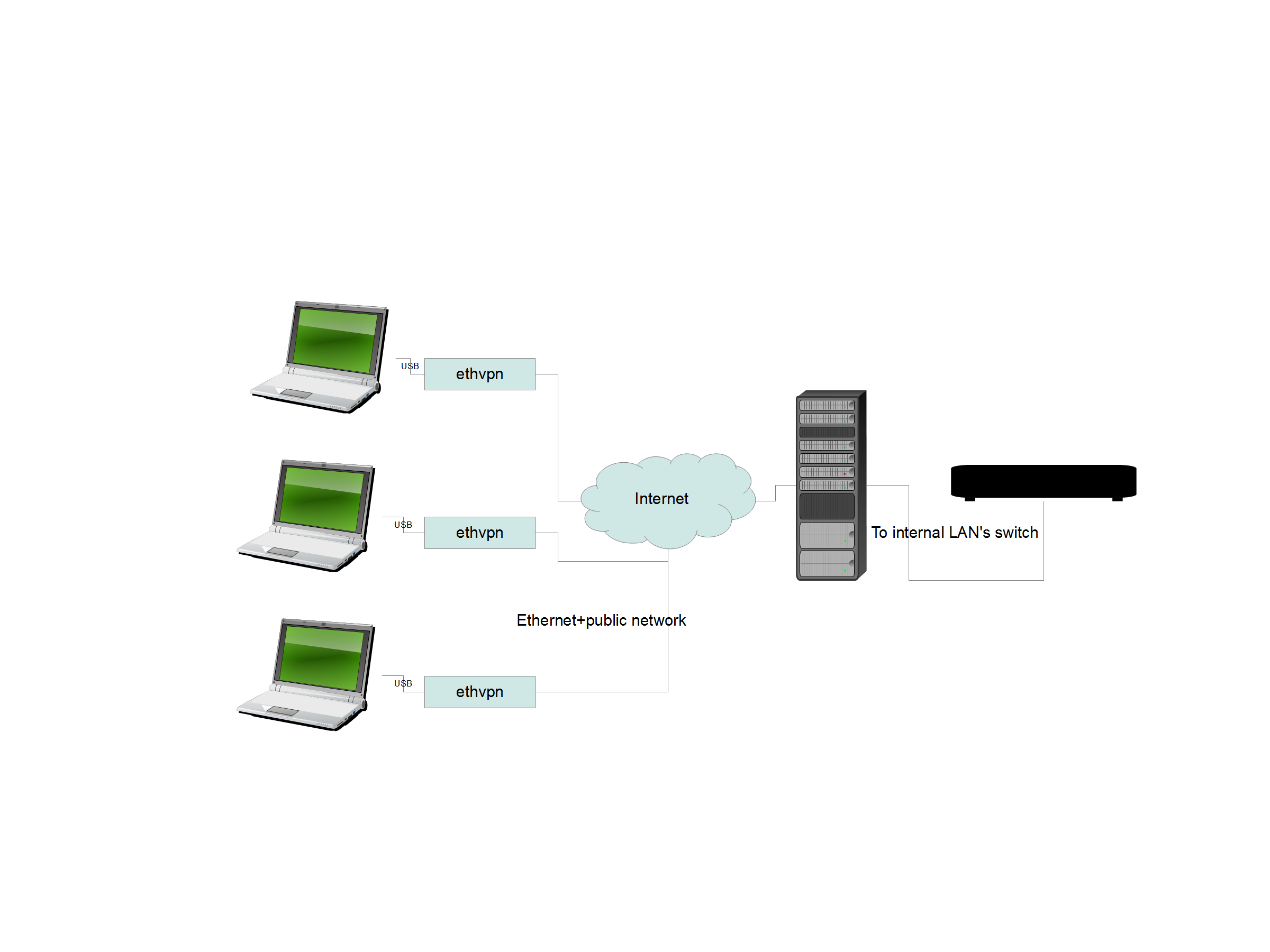
Some company has an internal network – most probably implemented as several Ethernet subnets. One of such subnets has a VPN entry server on it. The IT department issues each company's laptop holder an “ethvpn” adapter, preconfigured with entry's server public key and a unique private/public key pair, the public part of which is registered on the entry server – such that the server will recognize each client and route its ethernet packets onto matching virtual ethernet (TAP) interface.
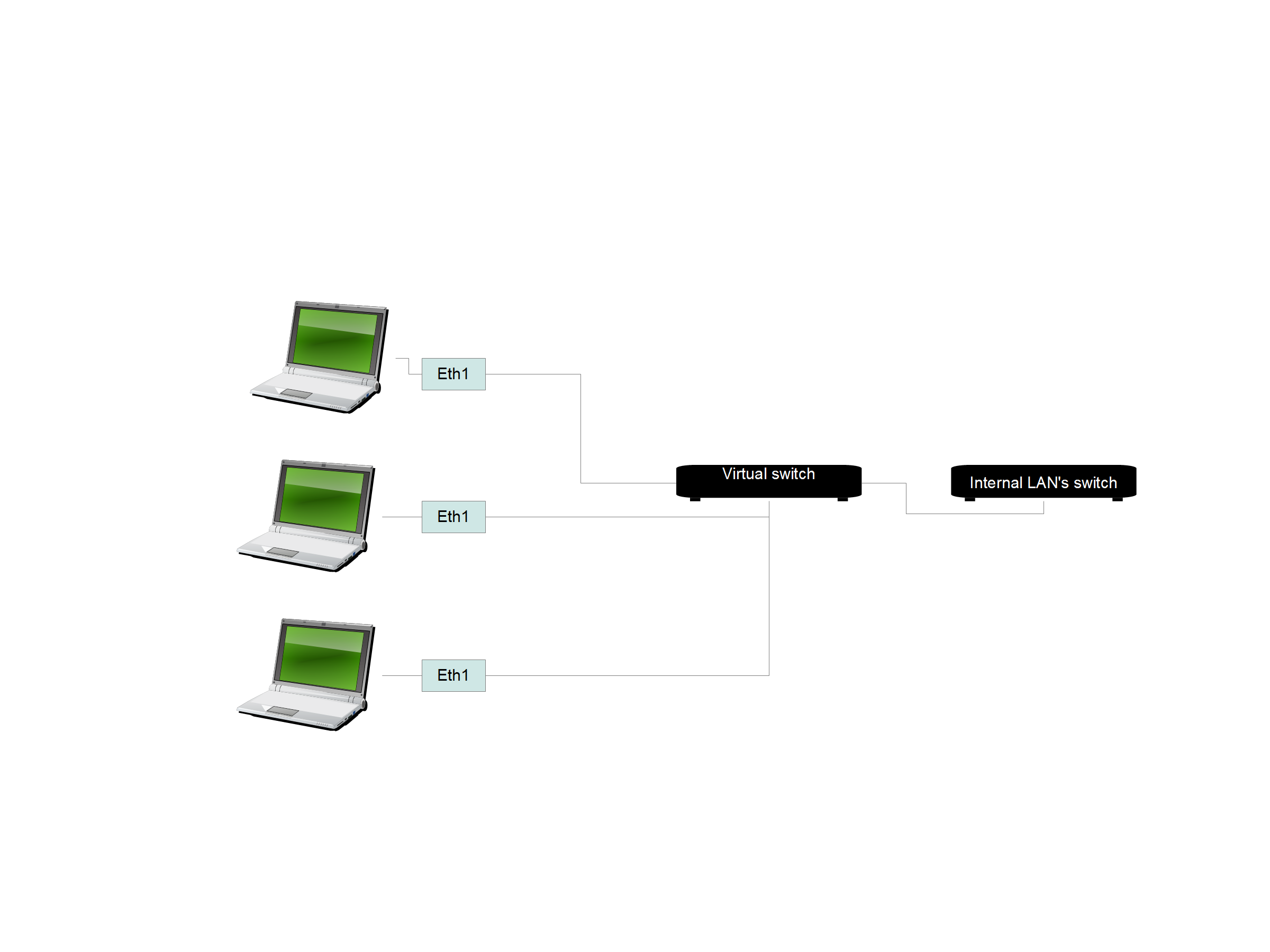
In this case the configuration chosen for the server would turn it into software switch, which switches packets between different remote client and possibly forwards them onto its single physical interface. (which is further switched by a real switch into a corporate network)
If the “ethvpn” adapters have been configured to use DHCP on the guest network and the VPN entry server forwards DHCP requests/responses properly to the virtual interfaces, then it is enough to connect an ethvpn adapter to the laptop on one side and to any public network on the other side to establish an encrypted and authenticated connection to a corporate network – while the user's software can't quite tell the difference from being directly connected to the corporate LAN. (The essential difference being obviously latency)
The physical network layout looks like this:

The logical layout is on the other hand:
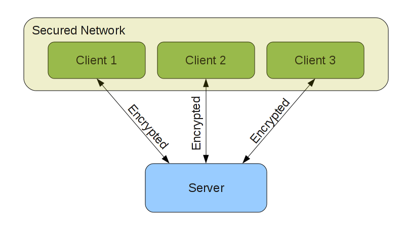
The goal of the whole system is to allow secure packet transfer between several entities. Several entities connect together to one shared network and within that network they are able to communicate securely with each other in a packet based protocol. Note that up to now there is relation to VPN at all.
Mentioned above shared network consists of a server and multiple clients. Each client identifies itself with a server (and vice-versa), and then it is able to send data packets to the server which forwards them to all currently connected clients (or to only one of the clients – this will be discussed later). The server thus acts simply as authentication entity and a hub that forwards data packets between several clients. Clients on the other side gain ability to transfer packets between each other, and to do this in the secured way (communication between client and server is encrypted).
The described above framework is used to implement our VPN protocol. The data packets transferred over the network will be Ethernet frames and since these packets are seen by all entities in the network, this network behaves exactly like LAN. There are two types of VPN clients – software client and hardware client. Both look identical to the server, but different to the client's machine. Software client creates virtual network interface (TAP in Linux) that serves as VPN interface and there a process that captures Ethernet frames from this interface, encrypts them, and sends to the server. Hardware client is completely transparent; the board connected via USB acts as a network adapter which is used by host as VPN network interface and everything else is done in hardware (the LPC2148 board).

Authentication protocol is very strict, it assumes that clients know server's identity and that server knows each client's identity. So in order to allow new client (previously unknown) to connect, there is a need to update the server's list of known clients.
The protocol is described in following diagram:

The protocol is invulnerable for man-in-the-middle attack as both client and server know each other's identity and verify this during the authentication. Note that the challenge string is not really required for authentication (used to validate server's identity), since if the server doesn't encrypt correctly the symmetric key, it won't be decrypted correctly by the client and in the end server won't be able to read the further data sent by the client. Still the protocol uses the challenge string, so that client could notice the problem during the authentication stage – this is convenient for error messages and debugging purposes. The same mechanism can be used vise-versa, i.e. server should sent a challenge string to the client in order to verify client's identity. But currently this stage is omitted since it has no security threat (malicious client won't be able to correctly decrypt the symmetric key) and it simplifies the protocol's implementation.
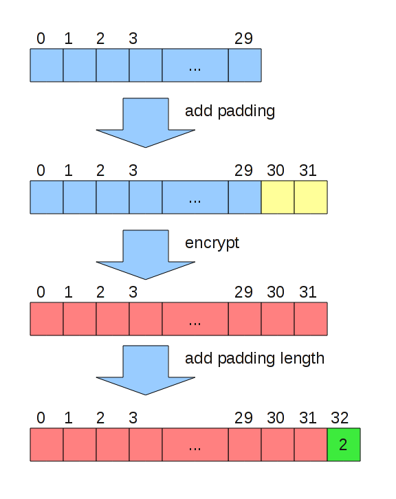
Encryption protocol is 128-bit AES in ECB mode (for simplicity). Each packet is padded to multiple of 16 bytes (block size of AES), then encrypted, and after the encryption one byte indicating the padding length is added, so that the decrypting side could remove the padding. Note that maximal overhead of this protocol on the packet length is 16 bytes.
The encrypted packets are transferred over TCP stream, so there is a need to indicate packet's start and end points in the stream. This is done by preceding each packet with 2-byte integer (in little-endian) indicating following packet's length. In order to prevent unnecessary fragmentation, we limit MTU of the VPN network to be 1442 bytes (1514 (physical) – 14 (Ethernet) – 40 (TCP/IP) – 16 (Encryption) – 2 (length header) = 1442).

The software side is written in Python. It uses a concept of Channel that refers to packet-based communication protocol. There are several types of implemented channels: UDP channel – trivial implementation over UDP, TCP channel – using 2-byte length header as above and Secure Channel – using described above encryption and authentication protocols (which is build over TCP Channel). Each channel has corresponding server side channel (except for UDP Channel) that is responsible for accepting incoming connection requests. For example server side TCP Channel simply accepts any TCP connection, while server side Secure Channel performs an authentication before accepting the client. All channels have the same interface, so it's very easy to change communication protocol between VPN server and software VPN client almost without any change at client and server's code. (The same is true for hardware VPN client – it has “layered” design as well, so it's easy to add/remove protocol layers)
VPN server maintains list of active channels to its clients and a server side channel (for accepting channels of new clients). It enters an infinite loop where it waits for an incoming packets from one of the channels and forwards them to other channels. Right now the forwarding strategy is simply to forward the packet to all channels except for the packet's source, so the server acts as a network hub. It's very easy to add a feature, that server will create a mapping between MAC addresses and active channels, so it could forward the packet to only one destination channel (and thus acting as network switch).
The client uses Secure Channel to connect and communicate with a server. It takes input packets and sends output packets to the virtual network interface (TAP). The actual implementation is a little different. To make the design more modular (mostly for testing purposes), the logic of communication with a server and logic of transferring the packets to/from TAP interface are split into two processes that communicate with each other using UDP Channel. One process vpnclient.py serves as a bridge between a Secure Channel with a server and a UDP Channel; other process stackfeeder.py serves as a bridge between UDP Channel and the TAP interface.
Components and their relation are summarized in the following diagram:
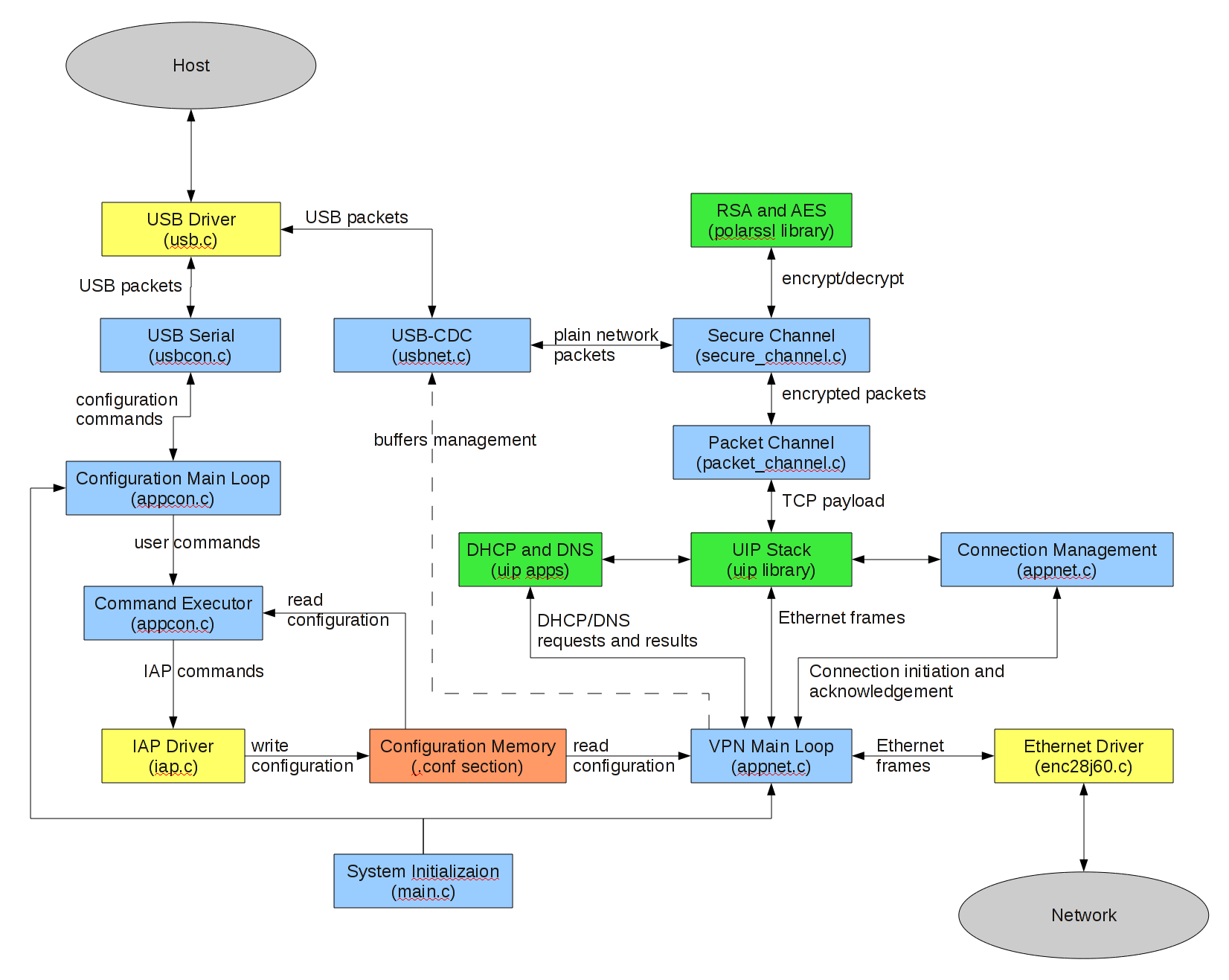
Main Loop – responsible for connecting all components together.
Makes a bridge between Ethernet driver and UIP stack.
Calls UIP periodic callbacks.
Initiates TCP connections.
Issues DHCP and DNS requests.
Manages USB-CDC driver (posting new buffers and freeing completed buffers).
DHCP and DNS. Both are supplied by UIP and used here without modifications. DHCP is used for address assignment on startup, and DNS is used for server's name resolution. Both features can be disabled, i.e. using static IP address instead of DHCP and by connecting to server using its IP address and not by name.
Connection Management. Connection management is responsible for initiating a TCP connection, making sure it's successfully connected and performing a reconnect if the connection was closed (reconnect will be attempted 1 second after the connection was closed).
Channels. There are Packet Channel and Secure Channel components. Both are designed in such way that they are unaware of each other, and of the underlying/above lying logic. This is achieved mainly by using function pointers to communicate with upper and lower layers. This communication interface is simple and consists of 4 functions: passing the packet to upper layer, polling the upper layer for new packets, passing the packet to lower layer and closing the lower's layer channel.
Packet Channel. Responsible for packets' encapsulation in the TCP stream. Most logic is actually in the decapsulation process, since a reassembly process occurs there.
Secure Channel. Implements authentication and encryption algorithms as described above.
USB-CDC Driver. This is a layer between the USB driver and the application that implements encapsulation of Ethernet frames in the USB packets (according to USB-CDC specification). This is the component that actually processes the interrupts from USB device. The interface of this driver to the application is by posting the data buffers either for sending or for reception, and the ability to poll these buffers for completion (i.e. buffer was completely sent, or completely received).
The device features special configuration mode. The device boots in either operational or configuration mode, the decision determined by activating hardware switch (joystick button) on the device. User intervention in configuration mode activation is crucial to avoid security breaches (so no host-side or network activation) as during configuration mode VPN host can be latered as well as private key retrieved.
In configuration mode the device identifies itself as USB serial device and can be used by the standard usbserial driver in Linux.
The configuration can be done with any generic tool capable of talking over serial port – including minicom and putty. The command interface is rather intuitive and has error handling and a help system (activated by the help command)
The device also ships with GUI configuration and diagnostics utility – it can determine which ethvpn adapters are connected in operational mode, and what network interface they bind to, as well as which devices are connected in configuration mode. Any device of the latter category can be configured through a dialog.
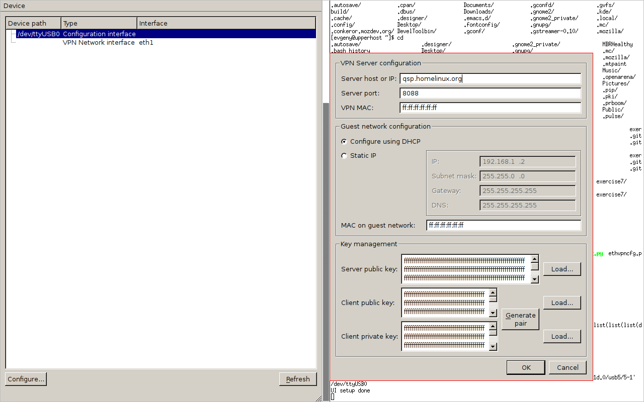
Illustration
1: Two devices are connected - one in configuration mode and one in
operational
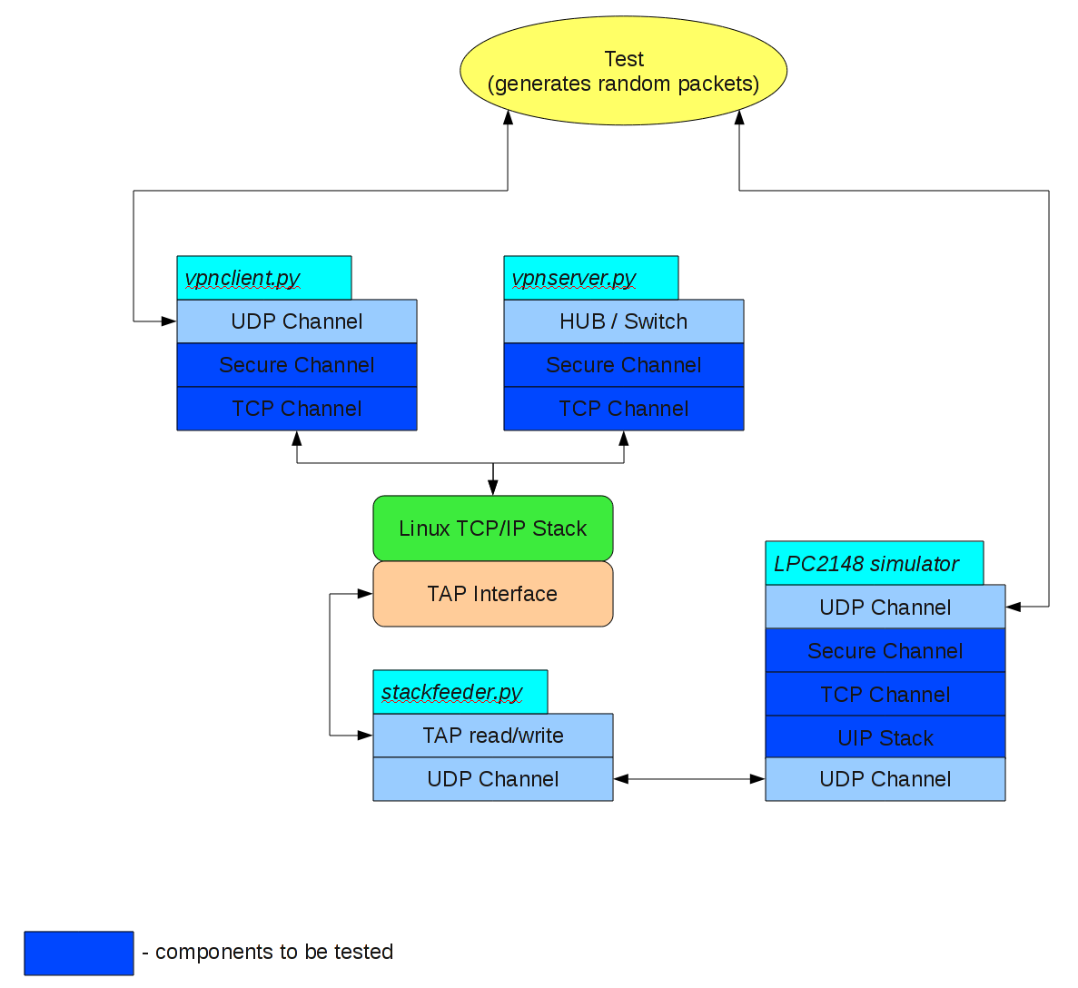
The logic of maintaining the VPN connection is pretty complex, thus having potential for bugs and on the other side it's not too bound to the actual hardware. So it would be nice to have an ability to run, test and debug this logic on the PC without uploading it each time to the device. The solution is pretty simple – we can replace the USB and Ethernet drivers (the only hardware the VPN logic uses) with something different and then compile and run the program on the PC. The functionality of the both drivers is sending packets to some media, so it is convenient to replace them by a driver that sends packets over a socket to some other process. This is exactly what was done – the new driver sends packets in UDP datagrams, and now they can be intercepted by a python script using the mentioned above UDP Channel.
As a reminder, the goal of the whole system can be viewed as a secure framework for transferring the data packets (building a VPN above it – it's just a usecase). Therefore we can test out code by building the following simulation environment:
Compare it with the real environment:
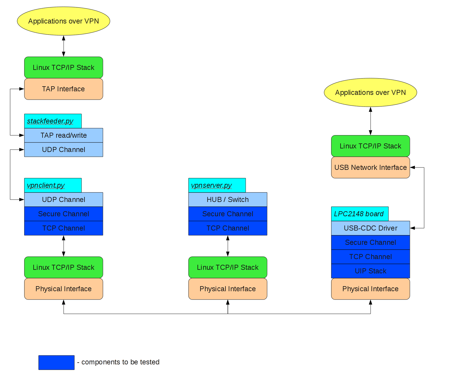
The key difference is that in simulation environment we don't encapsulate real network packets, but just a random data, and this is fine since the clients don't care of the actual payload they're encrypting and forwarding. Also note that the virtual network interface is used in both cases, but for completely different purpose: in the real environment it serves as a VPN, while in testing environment it is used to simulate the network stack on the server (so this virtual network stack actually communicates with UIP stack running in the simulator).
We used two projects from previous year as a base for our project. First was a USB network adapter implementing RNDIS interface to host, and the second was virtual Ethernet adapter (without the physical Ethernet interface) that used CDC interface to host (actually it supported both CDC and RNDIS). We used the first project for Ethernet driver and second project for CDC driver (as it is much simpler than RNDIS).
In addition we used two external libraries: UIP and Polarssl. UIP is a compact implementation of TCP/IP stack (designed for use in embedded systems), and Polarssl is a light-weight implementation of cryptographic algorithms. We used UIP to support TCP/IP stack in order to create TCP connections, and also for DHCP and DNS applications that were included there. Polarssl was used for RSA and AES algorithms.
Integration of the code from two projects from previous year wasn't trivial, mainly since the drivers' implementation was closely coupled with a main application code.
There was a bug in Ethernet driver that performed incorrect wrap-around of the frames buffer , thus leading to garbage packets being sent/received.
Polarssl library used dynamic allocations (in implementation of big integers that are used in RSA). We used a cross compiler gcc with a newlib C library. newlib supports dynamic allocations but it requires the definition of “end” symbol that is located at the beginning of the heap. We defined this symbol in the linker script and then the dynamic allocations worked fine.
ARM compilers apparently come in multitude of configurations, architecture support levels and ISA variations. One compiler provided by distribution which we employed didn't support thumb mode code and the IAP code is written in thumb. The problem manifested in mysterious crashes as the compiler had no courtesy to tell that the thumb code is not supported. (the hardcoded pointer ended in 1, signifying that the code must be in thumb instruction set) This was worked around by implementing glue code in assembly, to be invoked from regular ARM32 code.
We do not have a registered USB vendor ID and product ID and therefor are forced to use the “for development and testing purposes only” IDs generously provided by Wouter van Ooijen. The Linux's usbserial driver will treat any pair of bulk transfer end-points as potential serial device, however unfortunately it will ignore any devices whose IDs are not registered in it. The proper way to resolve this situation is to purchase an ID and to provide a patch upstream which will make usbserial recognize our configuration interface. The current workaround is to employ moduleLoad.sh script which reloads the driver with our Vendor ID and Product ID as module parameters.
The other significant limitation is that both VPN Ethernet (virtual) interface and a guest ethernet interface (the ethernet connection to the public network) require a unique MAC address. Currently we can just configure the MAC addresses as to avoid conflicts with surrounding hardware and this is fine for testing purposes but it's not a viable strategy for a commercial device.