Embedded Systems Course, Prof. Sivan Toledo
Tel Aviv University, 2011
Project by: Itay Berman [hotmail: itayberman], Omri Yariv [gmail: omriyariv]
Document Contents:
1. Description
The purpose of this project is to design and implement a protocol that enables use of the LPC2148 and its peripheral devices through standard IO methods from a connected terminal. The board will identify to the OS as a serial port and communication to it will be handled like one.
Current protocol implementation supports I2C and GPIO.
2. General Protocol Flow
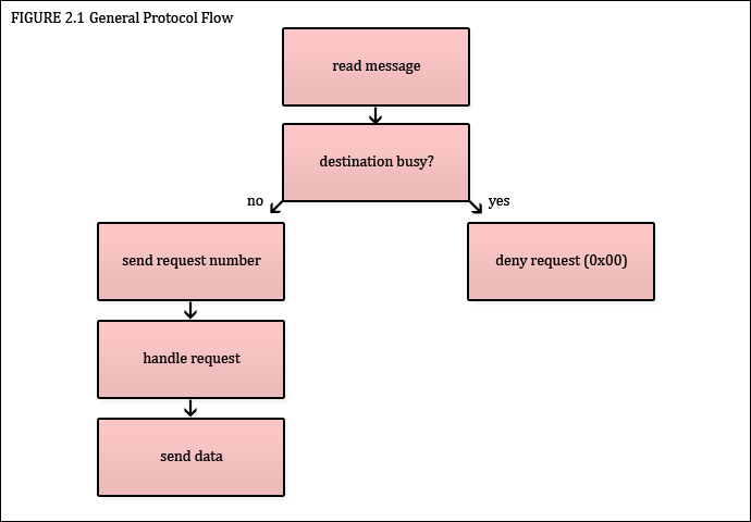
- Every message sent to the bridge protocol will contain in its first byte a destination protocol to which the request is intended:
- I2C – 0x01.
- GPIO – 0x02.
- Following the destination byte a request will contain several more bytes, depending on the destination protocol as describes below.
- Every request is assigned with a request number. The bridge protocol can decide to accept the request, or deny it. Upon request, the bridge protocol will return a single byte. If the request is accepted by the bridge protocol, the byte will contain the request number. If the request is denied, the bridge protocol will return 0. 0 will never be a request number.
- The request numbers are values between 0x01 to 0xfe, and are managed in a cyclic manner.
- The bridge protocol will return the request number or the deny message immediately.
- The bridge protocol will deny a request to a certain destination protocol if a previous request is currently handled by that destination protocol, and it is yet to return.
3. I2C Protocol
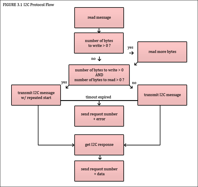
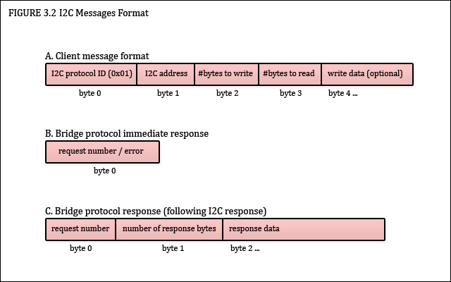
- The request message will contain at least 3 more bytes additional to the I2C destination protocol:
- I2C address byte.
- Number of bytes to write.
- Number of bytes to read.
- If the number of bytes is greater than 0, donate X, the user must supply X more bytes of data to write. If not, the user request is ended.
- When I2C bridge protocol message is accepted, the protocol will start a transaction through I2C on master mode. Each request will start a new transaction with I2C START mode. If both number of bytes to write and number of bytes to read are greater than 0, the bridge protocol will not release the I2C bus, but rather send the write bytes, send an I2C REPETED START, and will read bytes from the same I2C address.
- If the request was accepted, it is guaranteed that a response will be send. A request message contains at least 2 bytes:
- Request number (as the protocol returned as the immediate response for the request).
- Number of data bytes.
- If number of bytes to read in the request, denote Y, was 0, than the number of data bytes, denote Z, will be 0. If Y was greater than 0, then Z will be any number between 0 to Y.
- If Z is greater than 0, the response message will contain Z more bytes of data.
- If an error occurred while handling the request then Z will be 0xFF.
- Error may be cause due to:
- Timeout of I2C – if the I2C peripheral has yet to answer a request and enough time has elapsed.
- I2C internal error.
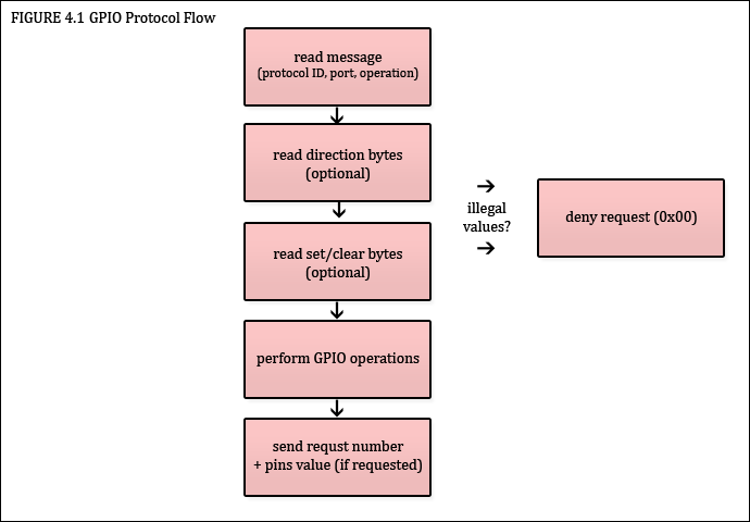
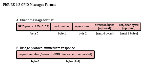
4. GPIO Protocol
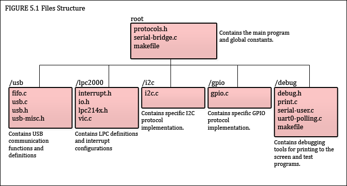
5. Implementation & Code
- The request message will contain at least 2 more bytes additional to the GPIO destination protocol:
- Port byte.
- Operation byte.
- Port byte will be either 0x00 for port0 of the GPIO, and 0x01 for port1.
- Operation byte will single desired operation:
- Set direction – 0x01.
- Set or clear bit – 0x02.
- Get pins value – 0x04.
- The port byte will be bitwise OR between all of the desired operation of the request.
- If set direction is wanted, then the user must supply 8 more bytes, right after the operation byte, in the following format:
- Bit x in the first 4 byte will be 1 if you want to set it to input.
- Bit x in the next 4 byte will be 1 if you want to set it to output.
- Bitwise AND of the first and next 4 bytes must be 0. If not, the protocol will return error.
- If set or clear is wanted, then the user must supply 8 more bytes, right after the 8 bytes of the direction, if the operation is wanted, or right after the operation byte, otherwise. The 8 bytes should be of the following format:
- Bit x in the first 4 byte will be 1 if you want to set it.
- Bit x in the next 4 byte will be 1 if you want to clear it.
- Bitwise AND of the first and next 4 bytes must be 0. If not, the protocol will return error.
- The GPIO bridge protocol is not blocking and is never in "busy" state, meaning the bridge protocol will perform the operation immediately, and return the result, without moving to the next command.
- If the request is valid the bridge protocol will return the request number.
- If the request is not valid as described in the above clauses, the brigde protocol will return an error.
- If the ‘get pins values’ operation is wanted, and the request is valid, the bridge protocol will return 4 additional bytes with the value of the pins in little endian order.
- Each of the operations is performed with a single access command to the GPIO registers.
5. Implementation & Code
- Source code can be downloaded here.
- Upon reset, the serial bridge protocol has a startup delay of 15 seconds. During this time, no request will be handled and communication may result in unexpected behavior. This is caused due to USB identification as a serial port to the OS.
- The LPC2148 is set to work at 24Mhz as the USB communication requires at least 18Mhz.
- I2C clock is set to 400Khz.
- The I2C timer is set to expire after 0.0125 seconds.
- Debug messages can be viewed with a special #define in debug.h. This requires a connected terminal through UART. Note that this feature adds a significant overhead at runtime.