Embedded Systems Course
Final Project
Smart House Emulator using Tmote-Sky
Developers: Tal Shapira & Max Gurtovoy
Course lecturer: Prof. Sivan Toledo
Winter semester 2012-2013
Goal
The goal of the project is to build a smart house – a computerized system for long distance control over a house.
The house's electric equipment is operated by Tmote-Sky MCUs. Each LED on the MCU emulates turning on/off an electric device.
The system's user/manager uses an Android application in order to control the system.
System Architecture
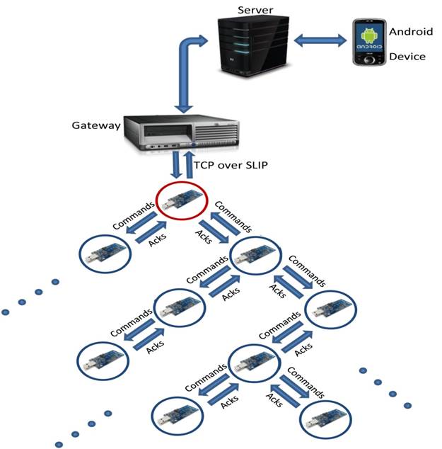
The architecture is demonstrated in the diagram below. The server (which has a static IP address) communicates with both the
Android application and the master Tmote-Sky node (the red circle in the illustration below) using the TCP/IP protocol. The master
Tmote-Sky node communicates with all other nodes with our RIME-based protocol that is explained later.
Challenges
> There is no NIC in the Tmote-Sky MCU.
Solution: the master node has to be connected over SLIP (Serial Line Internet Protocol) to a router that will forward packets to/from
the Android application.
> Absence of static IP address on the Android appliance and on the Tmote-Sky MCU.
Solution: connect as two clients (Android & master sky node) to a server with a static IP address. In this way we can deploy the
Tmote-Sky network anywhere we want.
> Signal strength limitations of the IEEE 802.15.4 Chipcon Wireless Transceiver.
Solution: use multi-hop communication primitives. The multi-hop primitives do not specify how packets are routed through the network.
Instead, as a packet is sent across the network, the application or upper layer protocol is invoked at every node to choose the next-hop
neighbor. This makes it possible to implement arbitrary routing protocols on top of the multi-hop primitives.
> Make the Tmote-Sky nodes communicate (between the master and the designated node) in a reliable way, using low power
consumption.
Solution: each command to the system is performed using a 3-step transaction as explained later.
> Build the Android application view in a dynamic way according to the number of nodes in the Tmote-Sky network.
Solution: extend the BaseAdapter abstract class. The BaseAdapter class implements the Adapter interface. The Adapter object acts as a
bridge between an AdapterView (view whose children are determined by an adapter) and the data for that view (data that is determined
dynamically).
System Flow
1. Server with static IP address listens for TCP connections from the master node client (i.e Contiki client) and from the Android application
(i.e. Android client).
2. Contiki client connects to the server.
3. Android client connects to the server.
4. Server waits for messages from the Android client to forward to the Contiki client.
5. Android client queries for the number of nodes in the system in order to build the application view.
6. Server forwards the query to the Contiki client (master node) and waits for an answer.
7. Contiki client (mater node) sends the answer to the server.
8. Server sends the answer to the Android client and waits for commands from it.
9. Android client builds application view and waits for user input (clicks on the relevant buttons).
10. User clicks a button to cause a change of state at some node in the network.
11. Android client sends the relevant command to the server and waits for ack.
12. Server receives the command, forwards it to the Contiki client and waits for ack.
13. Contiki client receives the command and sends it to the relevant node in the network.
14. Relevant node receives the command and performs the needed action. Then it sends an ack to the Contiki client.
15. Contiki client receives an ack from the node in the network, and then sends a “stop flooding” message to the network, and an ack to the
server.
16. Server receives the ack and forwards it to the Android client.
17. Android client receives the ack and becomes available for user commands again (back to step #10).
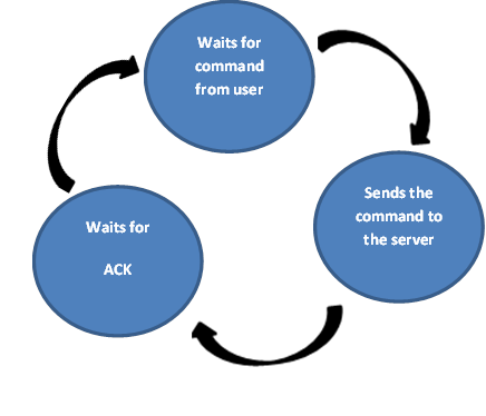
Android Client Flow
 |
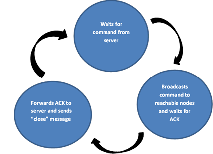
Contiki Client (Master Node) Flow
 |
Multi-Hop Protocol Explanation and Demonstration (Using Cooja Emulator)
To implement the system communication we relied on Contiki Trickle (RIME-based single source flooding) and changed it for our needs.
Each command received by the master node from the server is followed by a 3-step transaction.
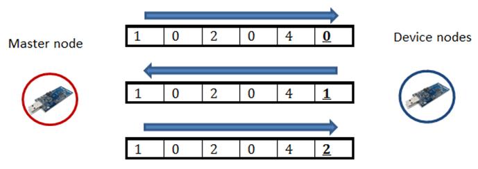
In each step a message is flooded in the system. Each message contains (from left to right in the diagram below):
2 cells of source Id (master node), 2 cells of destination device node id, 1 cell of operation id (e.g. “4” in the diagram, meaning
“turn the blue LED on”), and 1 cell of message status. At first the master node sends a command with status 0, and when the
designated node receives the command it performs it and changes the status to 1 (ack message). When the master node receives the ack
it floods a "close" message in the system. Each node forwards this message a predefined number of times and then stops all forwarding,
it "sleeps" until a new command arrives.
Each small circle with a number (in the diagram below) represents a node in the network.
The green circle represents the transmission range of the node transceiver.
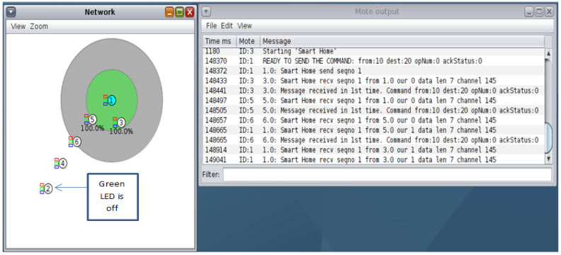
Step 1 – master node (node #1) sends the command “green LED on” to node #2.
Initial state: Green LED on Node #2 is off.
Node #1 floods the message in the network.
Node #5 receives the message and floods it too.
Node #6 receives the message from Node #5 and floods it too.
Node #4 receives the message from Node #6 and floods it too.
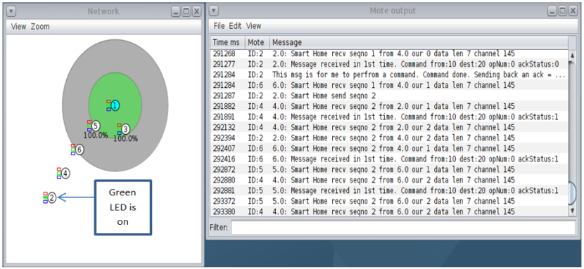
Step 2 – node #2 receives the message
Node #2 receives a message “green LED on” from Node #4.
Node #2 performs the command.
Node #2 floods an ack message to node #1.
Node #4 receives an ack from node #2 and floods it in the network.
Node #6 receives an ack from node #4 and floods it too.
Node #5 receives an ack from node #6 and floods it too.
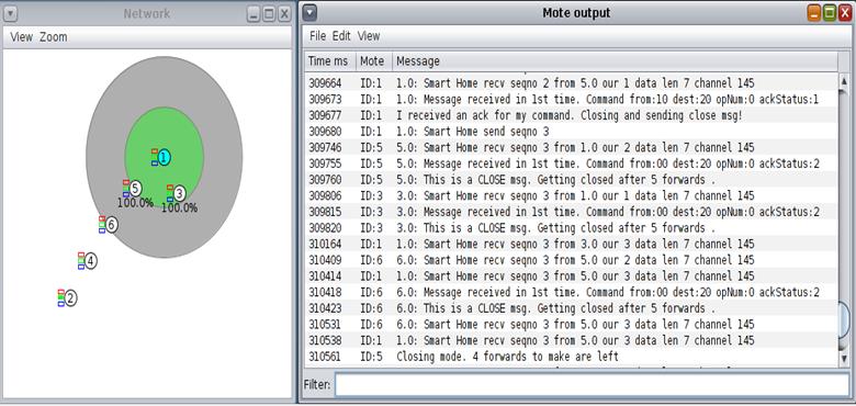
Step 3 – Node #1 receives the ack and sends a “CLOSE” message to the network
The “CLOSE” message tells the nodes to stop flooding the current message and move to the “resting” state.
Node #1 receives an ack from node #5 and sends a “CLOSE” message to the network.
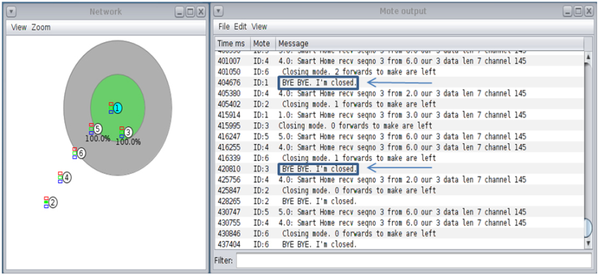
The network nodes move to the “resting” state
The “CLOSE” message is flooded in the network and all nodes close the session for this command by saying:
“BYE BYE. I’m closed”.
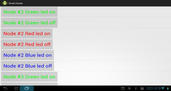
Android Application (for Platform 4.0.3 and Above)
As we mentioned earlier, the Android application connects as a client to a server with a static IP address. The first message
after the connection is a query to the master node in the Contiki network for the number of nodes in it. After receiving the
answer the application builds the main user interface:
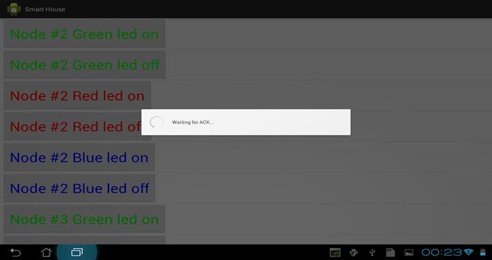
Now the user can press on a button to perform the desired action. After pressing a button the application sends the relevant
command to the relevant node (through the server and the Contiki client) and waits for ACK:
Future Possibilities
> Connect the network nodes to real house equipment to enable the user to control real home devices.
> Add a NIC to the master Contiki node in order to get rid of the server that is the bottle neck in the current configuration.
> Develop an iOS application to control the Contiki network.
Resources
Contiki OS - http://contiki.sourceforge.net/docs/2.6/index.html
Get started with contiki - http://www.contiki-os.org/start.html
Contiki uIP TCP/IP stack - http://senstools.gforge.inria.fr/doku.php?id=os:contiki
Linux network configuration - http://www.yolinux.com/TUTORIALS/LinuxTutorialNetworking.html
Android training - http://developer.android.com/training/index.html
Tmote-sky datasheet - http://www.eecs.harvard.edu/~konrad/projects/shimmer/references/tmote-sky-datasheet.pdf