Gesture Controlled Car
By:
Gal Lerman, Mor Baruch, Matan David.
Instructor:
Prof. Sivan Toledo
Embedded Systems Course
Tel Aviv University, 2014
Project Goal:
Remote controls cars are all the same. You can go right, left, forward or backwards. But how much fun would it be if you could control the car by simple, more intuitive, hand gestures. That is what we set out to do.
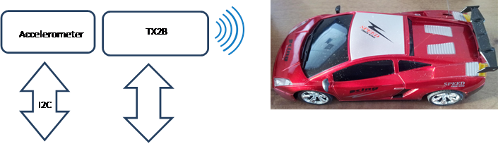
General Description:
Our project is composed of one Arduino Uno board, a remote
control car, and accelerometer. The remote control is connected to the Arduino
board by soldering the forward, reverse, right and left buttons to designated
output ports (7,8,12,13). The accelerometer, working
with the ![]() protocol is connected to the Arduino using
the designated ports A4 and A5, one for the SCL and the other SDA. The Arduino
outputs the necessary voltage using the 5V ports for the remote control circuit
and the 3.3V for the accelerometer. The Arduino is connected to one 9V battery.
protocol is connected to the Arduino using
the designated ports A4 and A5, one for the SCL and the other SDA. The Arduino
outputs the necessary voltage using the 5V ports for the remote control circuit
and the 3.3V for the accelerometer. The Arduino is connected to one 9V battery.
The Arduino reads the inputs from the accelerometer, using the X and Y axis. When the G force is greater/less than a predefined value, the Arduino translates this value to an “Active Low” output signal on the corresponding pin of the remote control circuit. Using the accelerometer gives us the ability to set the sensitivity of the hand motion that controls the car.
System Flow:
System Image:
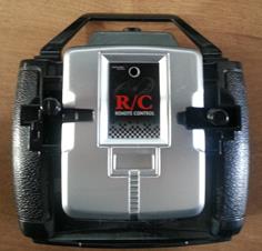
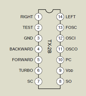
Remote Control:
The remote is controlled by a TX2B chip.
After researching the chip we found that direction button is “Active Low”. In
addition, the operating voltage of the circuit is 5V, and since the Arduino is
able to output this level, we were able to disconnect the circuit from the
delivered casing, and connect it directly to ours. We soldered pins 14,1,5 and 4 to the digital output pins of the Arduino
7,8,12,13 respectively. We configured the Arduino to output “0” on each pin
when the correct signal from the accelerometer is received.
Old Remote control picture:
Remote Control Pin Configuration:
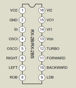
Car Pin Configuration:
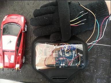
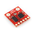 Accelerometer:
The ADXL 345 Accelerometer measures
acceleration, often caused by motion. But when they are standing still, the
only acceleration the accelerometer senses is due to gravity pulling down on
it. In our circuit we measured the static acceleration of gravity on 2 axis, the X and the Y. When connected, the accelerometer is
attached to our palm, where the initial state is that both the X and Y axis
feel zero gravity force. When turning our hand to the right, the gravity on the
Y axis starts increasing. We decided on G force of +2 as the point where the
Arduino should interpret this as a right turn. We could have chosen a higher or
lower value, and this would change the sensitivity of the hand gestures. By
symmetry, when turning our hand left, the G force of the Y axis decreases to a
negative number, and the threshold we chose is -2. The same goes for the X axis
and when we drop or raise the wrist of our hand.
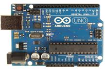
Arduino:
We used an Arduino Uno and coded it to
translate signals received from the accelerometer to output signals to the TX2B
chip. Using the Arduino datasheet, we connected the accelerometer through pins
A4 and A5, and the remote control to digital output pins 7,8,12 and 13. We used
the Arduino.exe app and the Arduino interface to code the wanted functionality.
Arduino Picture:

The Arduino reads the G force signals
from the accelerometer, and when receiving a G force that passes one of the
defined thresholds (![]() G), it outputs “Active Low” on the relevant
port. The outputs activates the pin of the TX2B
transmitter chip and is then transmitted to the receiver chip.
G), it outputs “Active Low” on the relevant
port. The outputs activates the pin of the TX2B
transmitter chip and is then transmitted to the receiver chip.