UART plug&play
Simply plug a UART supported devices and the Datalogger will start logging.
Logging configuration, including message size and baud-rate, can be easily modified in the code.
Allows you to log any data from external source
and download it at the touch of a button
Datalogger is a power-failure resistant firmware that allows continuous logging of data from external source, which then could be downloaded at the touch of a button. It is implemented on the TI CC2650 LaunchPad, where the data is stored on an external flash, and being downloaded over BLE.
Here, we demonstrate the Datalogger firmware with another chip, which measures temperature at intervals.
Simply plug a UART supported devices and the Datalogger will start logging.
Logging configuration, including message size and baud-rate, can be easily modified in the code.
The firmware is fully recoverable from an unexpected power shut-down.
The data is stored on a non-volatile flash chip, hence, it is being kept intact until you download it.
Easy connection over BLE to retrive the saved data. The connection is secured with a pin code.
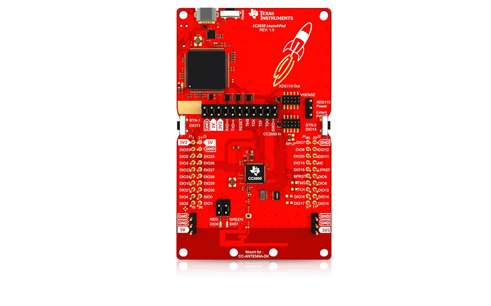
The CC2650 LaunchPad is a TI evaluation board.
The board comes with BLE capabilities and support multiple communication protocols, including UART and I2C.
It has various build-in sensors and indicators, such as LEDs and temperature sensor.
Furthermore, it has a Macronix MX25R8035F flash memory chip of 8Mb.
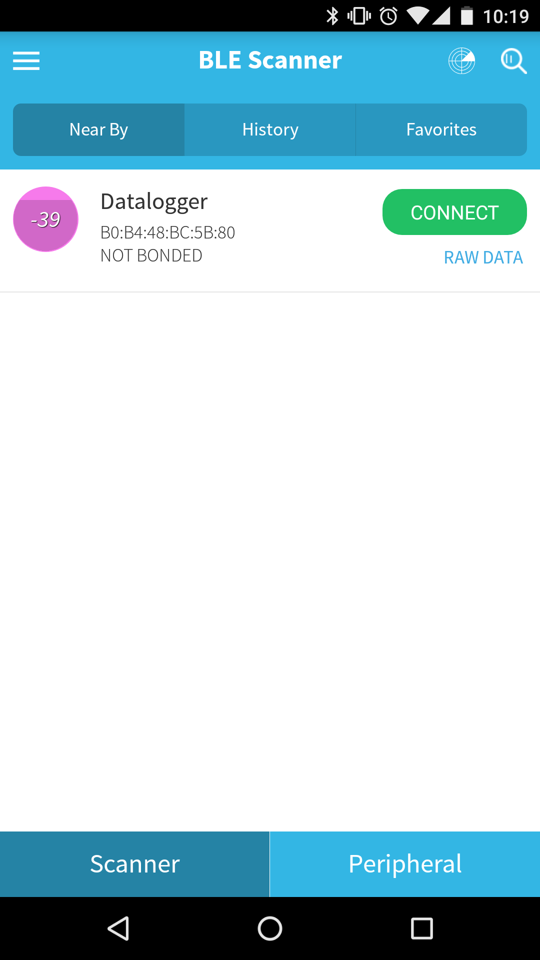
The Datalogger exposes a BLE data service, through it, one can download the data to its smartphone, or other device which supports BLE.
Here, we used the BLE Scanner
application for Android.
Alternatively, one can use any other BLE application, for example SensorTag and LightBlue for iOS.
Currently, those applications do not store the downlowded data, but only supply an interface to use the BLE service, and visulize the downloading process.
Here, we used a second TI CC2650 LaunchPad device, as a temperature sensor.
By utilizing the CC2650 LaunchPad's build-in BATMON module, we generate temperature measurements within the range of -256c to +255c.
This external data source could be replaced by any sensor or firmware, which supports connections over UART.

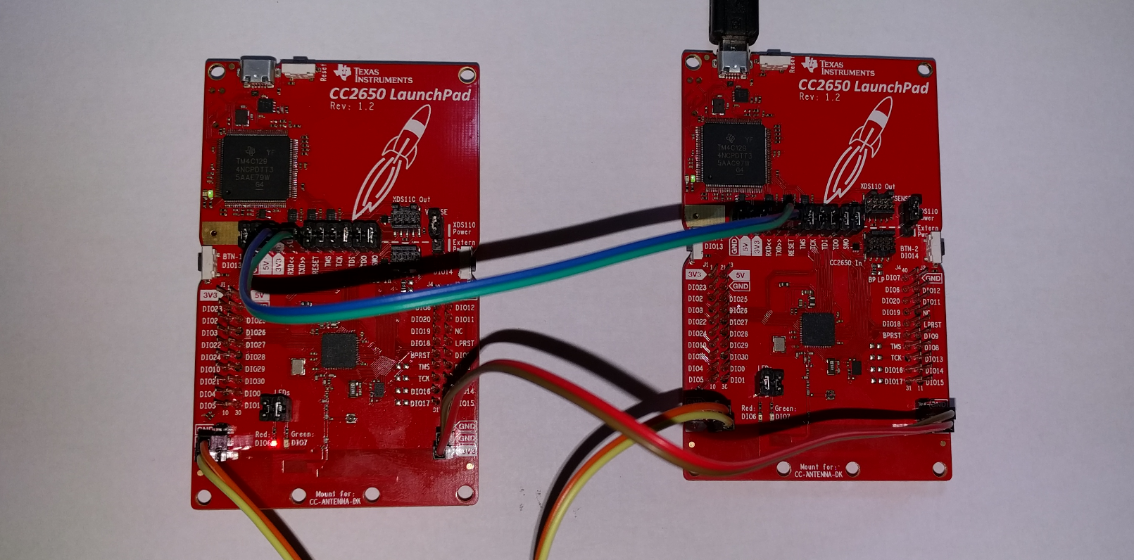
Setup Diagram
To enable UART connection, the RX/TX pins of the Datalogger are respectively connected to the TX/RX pins of the data-source device. To prevent interference, the devices' GRD have to be connected as well.
It is possible to connect the Datalogger to more than one UART source. The Datalogger cannot distinguish between the different sources and will treat all the messages the same.
Note: in a multiple-sources situation messages collision may occur.
Communication Interface
The Datalogger waits for incoming UART messages. Its settings are configured to baud-rate of 115200 and message size of a single measurement.
Message Handling
Upon incoming message, the UART callback is executed. Once arrived, the message is pushed to the queue and the green LED is toggeled. Following that, the semaphore upon which the UART task is pending on is posted.
The UART task dequeues one message at a time. Each message is then stored to the external flash memory.
Data Storage
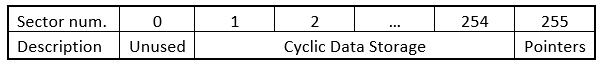
For data storage, the Datalogger uses the address space between 0x1000 and 0xFEFF0.
This address space is divisible by 8, which represents the measurement size in bytes, thus providing an aligned file structure.
We have not used the first sector since it contains OTP area.
The last sector is dedicated to Power Failure Resistance section (see below).
The address space stated above is considered as a single file, where data is written in a cyclic manner.
Power Failure Resistance
When the program is first uploaded to the MCU, we run a unique initialization code that sets the cyclic pointers, which are located in the last sector.
The pointers are updated upon either write operation or BLE indication acknowledgement, to provide power failure resistance.
Communication Interface
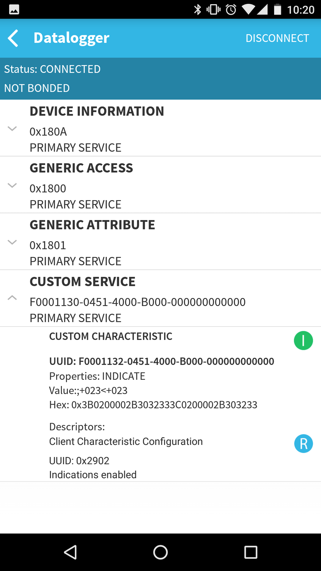
The Datalogger exposes a data service, which allows to download the stored data from the flash. The service comprises a single characteristic, with an "Indicate" property. Registration to this characteristic initiates the downloading of the data, which is being sent through indications.
Every indication has maximum length of 24 bytes, which cover 3 data measurements in our case, since every measurement is of 8 bytes size. As the default ATT_MTU value is 23 bytes, we increased the MAX_PDU_SIZE parameter, accordingly.
Data Integrity
By using indications, an acknowledgment is sent back for every indication received by the peer device. In our implementation, data integrity is guaranteed by sending the next indication only when the privious one has been acknowledged.
Moreover, data is being erased from the flash, only after it has been acknowledged.
Concretly, the first indication is sent immidiately after a registration event from the peer device. Every following indication would be sent after receiving a GATT event ATT_HANDLE_VALUE_CFM.
Security Measurements
Connecting to the Datalogger requires a pincode, which is hardcoded in the firmware. Any attempt to download the data without providing the pincode would fail, as the service characteristic requires an authenticated connection.
Authentication is required for per every connection to the Datalogger, as every bond of a peer device is erased upon a disconnection.
Datalogger supports only one connection at any given time.
Temperature Measurement
Every 10 seconds a clock interrupt awakens the MCU. Once up, a measurement of the surrounding temperature is taken, using the build-in BATMON module. To indicate temperature measuring, the red LED is toggled.
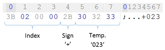
Message Structure
The message consists of two parts with a total length of 8 bytes.
The first 4 bytes represent the index assigned for the measurement. When the index reaches maximum value, it wraps-around back to zero.
The last 4 bytes are the temperature measurement, taken from BATMON module and converted to a string.
You can find our project on GitHub

There are two tasks running on the Datalogger device, both using a shared resouce (the external flash) and global pointers.
While the UART task receives data from the external source and writes it to the flash, the BLE task,
reads that exact content from the flash and sends it to a peer device.
In order to provide safe access to the flash, we designed a solution that ensures no task preemption during I/O operations and pointers updates.
The UART task runs in a higher priotity (priority 2) than the BLE task (priority 1). When the BLE task needs access to the shared resource,
it raises its priority to be the same as the UART task's priority.
Having the same priority, the two tasks can not preempt each other. Hence, safe access is guaranteed.
During a BLE session, the UART callback still accepts messages and pushes them to a dedicated queue.
Once finished, the UART task is geared into action and process the queued messages.
This project was created as part of an "Advanced Computer Systems" course
at Tel Aviv University led by Prof Sivan Toledo.
![]()