Range Detection System
Abstract
The following project was done as part of
“Advanced Computer Systems” course, fall 2017,  Tel-Aviv University.
The project main objective is to successfully
integrate a laser-based close-range measurement sensor to our TI CC1350 board
via I2C communication protocol and be able to send
measurement data via Bluetooth to a mobile device.
This prototype can set the basis for future
development of various applications such as an obstacle detection for the
blind, obstacle avoidance for drones etc.
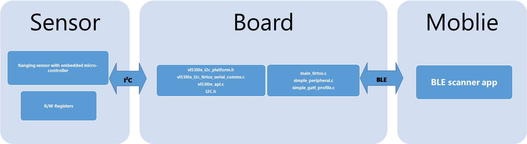
System Architecture
The system is
built of 3 main modules:
1. Board -
CC1350 SimpleLinkTM Wireless MCU Launchpad.
2. Sensor - VL53L0X Time-of-Flight Distance Sensor
Carrier, 200cm Max.
3. Mobile device with BLE support.
Sensor
The VL53L0X from ST Microelectronics is a time-of-flight
ranging system integrated into a compact module. It uses ST’s FlightSense technology
to precisely measure how long it takes for emitted pulses of infrared laser
light to reach the nearest object and be reflected back to a detector, so it
can be considered a tiny, self-contained lidar system. This time-of-flight
(TOF) measurement enables it to accurately determine the absolute distance to a
target without the object’s reflectance greatly influencing the measurement.
The sensor can report distances of up to 2 m (6.6 ft) with 1 mm
resolution, but its effective range and accuracy (noise) depend heavily on
ambient conditions and target characteristics like reflectance and size, as
well as the sensor configuration. Ranging measurements are available through
the sensor’s I²C interface, which is also used to configure sensor settings
The carrier board includes a low-dropout linear voltage
regulator that provides the 2.8 V required by the VL53L0X, which allows
the sensor to be powered from a 2.6 V to 5.5 V supply.
Specifications:
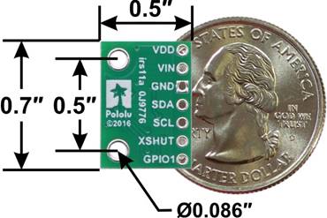 Dimensions: 0.5″ × 0.7″ × 0.085″
(13 mm × 18 mm × 2 mm
Dimensions: 0.5″ × 0.7″ × 0.085″
(13 mm × 18 mm × 2 mm
Weight
without header pins: 0.5 g (0.02 oz)
Operating
voltage: 2.6 V to 5.5 V
Supply
current: 10 mA (typical average during active ranging)
Output
format (I²C): 16-bit distance reading (in millimeters)
Distance
measuring range: up to 2 m (6.6 ft)
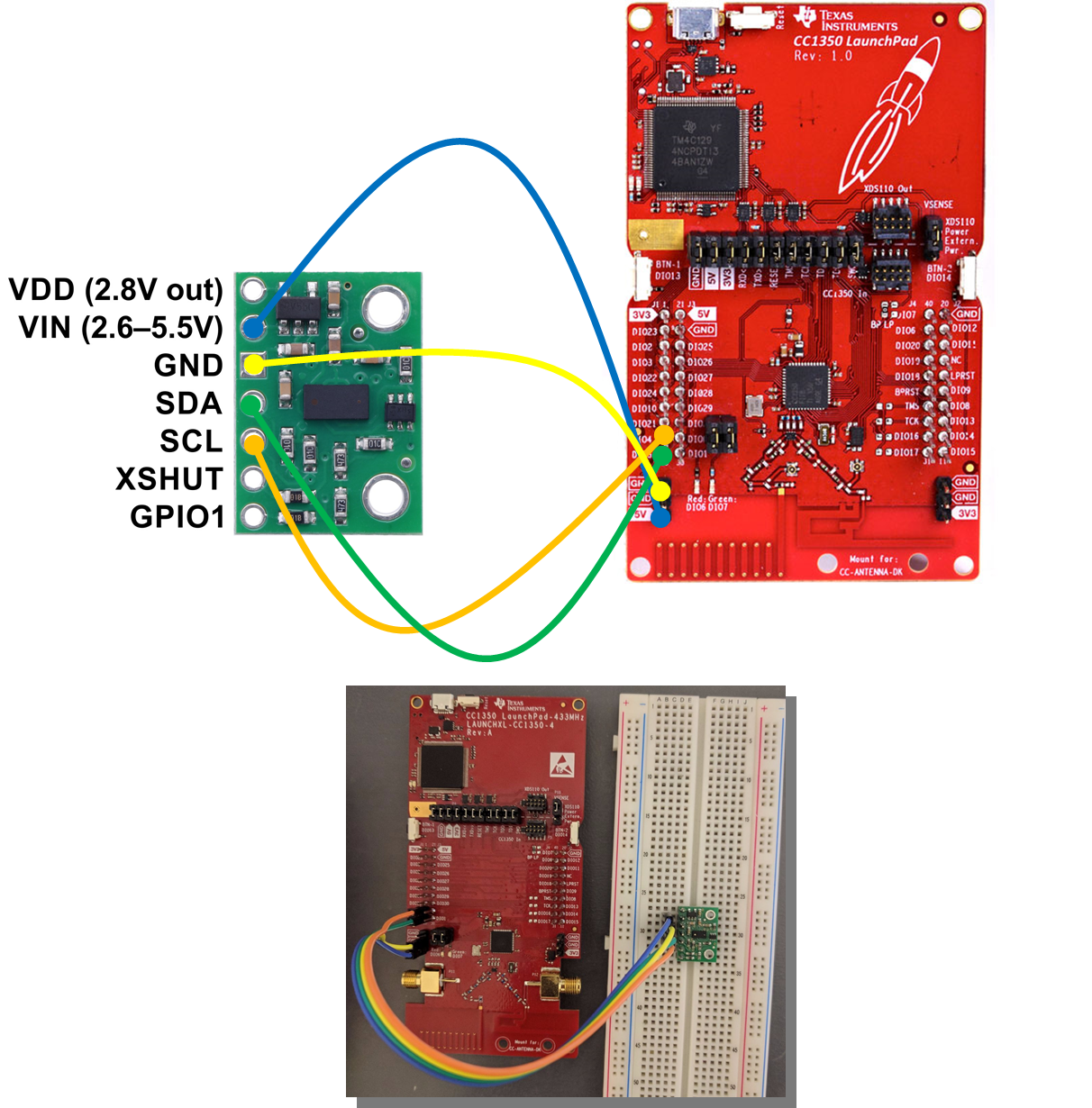
Board-Sensor Integration
4 minimal
connections are required in order to integrate the sensor to the board:
1. VIN sensor pin
is connected to the 5V board pin.
2. GND sensor pin
is connected to GND board pin.
3. SDA (data
line) sensor pin is connected to DIO4 board pin.
4. SCL (clock
line) sensor pin is connected to DIO5 board pin.
Software
I2C:
In order to port the VL53L0X given API, we
needed to implement the I2C communication protocol to fit to our specific
board platform. To do so, we created the source file “vl53l0x_i2c_tirtos_serial_comms.c”
that implements the following functions (described in
“vl53l0x_i2c_platform.h”):
•
Int32_t VL530X_i2c_init();
•
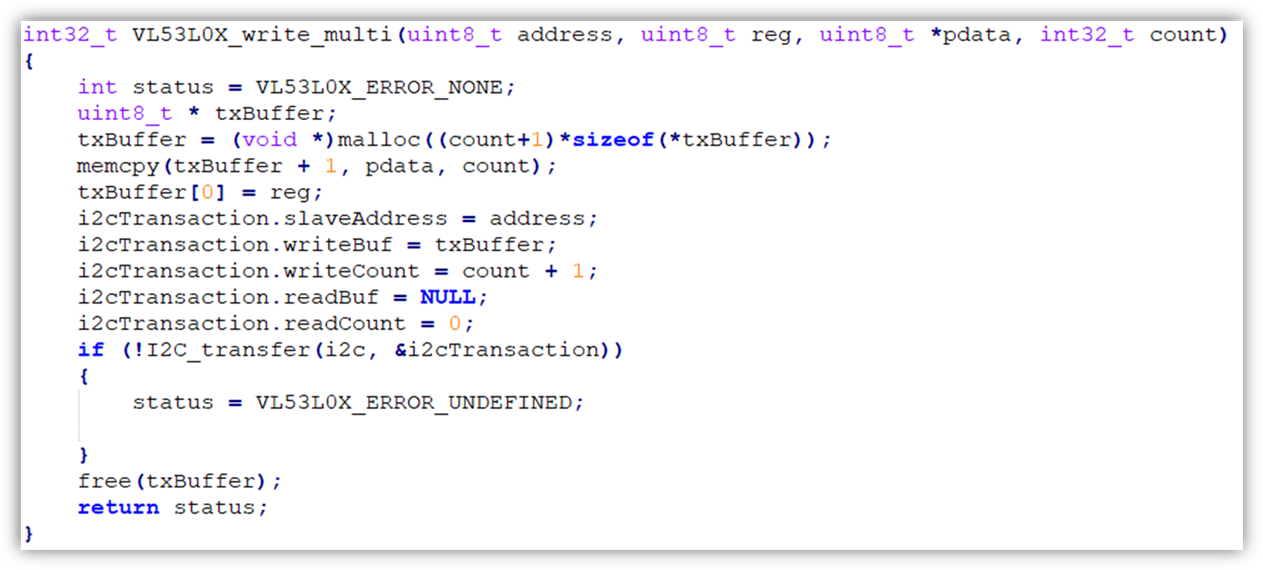
int32_t VL53L0X_write_multi(uint8_t address,
uint8_t register, uint8_t *pdata, int32_t count);
•
int32_t
VL53L0X_read_multi(uint8_t address, uint8_t index, uint8_t *pdata, int32_t
count);
•
Int32_t VL530X_comms_close();
The TI-RTOS I2C API provides 3
types of transactions – Read, Write or Write&Read. A transaction’s parameters include the slave
address, and a buffer to be written or read from. However, it does not include
a register-address parameter, i.e. in order to implement the needed functions
as described above, we needed to follow the I2C protocol in the
following way:
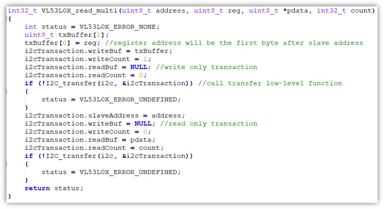
· The read
function – will consist 2 transactions. First a write address to specify the
register address, and second is the actual read transaction to read register
content:
·
The write function – one write transaction,
with one byte added in the beginning to specify the register address:
BLE:
We based on the Simple_peripheral example
project given by TI with the following main changes:
· The
initialization code for the I2C and the sensor was “pushed” into the
initialization phase of the BLE. By so, the program, and specifically the
sensor’s measurements, will only start after a “trigger” caused by a mobile
device Bluetooth connection attempt.
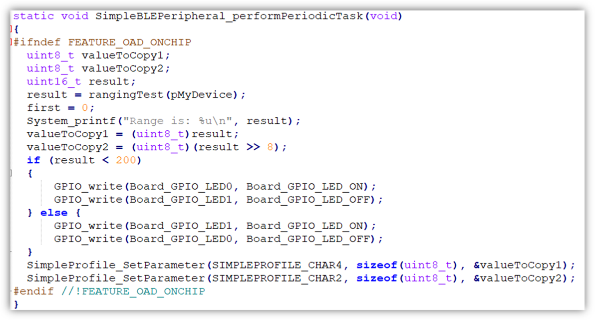
· The
get_single_measurement call was added to the periodic task (after reducing the
period time). By so, around every micro-second a range measurement will be sent
to the BLE device.
· The data sent
after the Set_Parameter call is restricted to only one-byte length. This caused
a difficulty, for the sensor provides measurement date of two-bytes length (to
achieve the maximal range of 2000 millimeters). In order to solve this issue,
we added one more Notification characteristic in the Profile code and split the
one 16-bit data into two 8-bit data and sent both bytes in parallel to the two
different attributes.
· Lastly, we
added a visual aid, using the on-board LED lights to indicate the close range
of 20 centimeters. By so, when the measurement data is less then 20
centimeters, the red LED light will turn on, otherwise, the green LED light
will light.
Demonstration
Development challenges
During the
work on the project, we came across many challenges. We will present the top-5:
1. We wrecked a sensor during a failed soldering
attempt. The important lesson, is that we discovered that by measuring the
voltage levels in the sensor’s inputs. Make sure that the input voltage is in
accordance to the given voltage in the board’s output. (5v for vin, 0 for GND,
and around 3V for SCL and SDA).
2. Slave address: According to the sensor’s datasheet, the
slave addresses of the sensor are 0x52 and 0x53 (for read and write). However, these
are not the actual addresses you need to give the I2C TI-RTOS API as
address. The actual address, as calculated by the driver, consists of only
the high 7 bits (without the R/W LSB) and pads the LSB according to whether it
is a read or write transactions. Therefore, the correct address we finally
used, is 0x29 for both read and write, the driver completes the rest.
Initially, before we understood that we have the wrong address, we were not
sure whether the board is actually executing a transaction. We used a scope to
measure the voltage level at the SDA and SCL outputs, to make sure that a
transaction is actually happening and received the following plot:
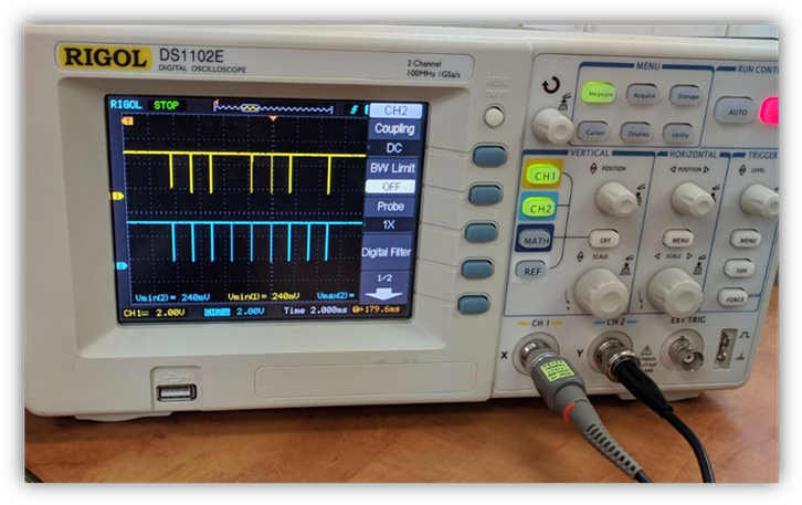
According to
this plot, we came to realize that the board is sending a slave address on the
bus, with no reply, and realized that the issue is in the slave-address.
3. After solving
the address issue, the program was stopping and we couldn’t realize why. After we
came across a recent forum describing a similar issue, we realized that a
driver update was needed. At the end, the SDK version that is working is
1_60_00_21.
4. According to
the I2C TI-RTOS API, there is another way to send a read request
(without a double transaction as we eventually used), by sending a Read after
Write transaction. This merge both transactions into one. This method is not guaranteed
to work with every sensor (as mentioned in TI forum).
5. After resolving
last issue, the program was still not completing, and stopped after few
transactions. After a lot of debugging, we realized that after a lot of calls,
the stack was filled and the program stopped. We doubled the stack size of the task
by two, and it resolved the issue.
Source code
https://github.com/orelbenish/RangeDetectionProject.git
References
https://www.pololu.com/product/2490
https://www.pololu.com/file/0J435/UM10204.pdf
https://www.pololu.com/file/0J1188/vl53l0x-time-of-flight-distance-sensor-carrier-schematic.pdf
https://www.pololu.com/file/0J1194/vl53l0x-carrier-dimension-diagram.pdf
https://www.pololu.com/file/0J435/UM10204.pdf
http://processors.wiki.ti.com/index.php/CC26xx_Ouput_TI-RTOS_Log_statements_over_UART