Advanced Computer Systems project
Remote task loading for CC-1350
Ofir Cohen / Dima Kuznetsov, Fall 2018
The main goal of our project is to allow a developer to push new code to the board over the air (Bluetooth Low Energy). The rationale behind this project was to allow downloading updates of the sensor software and swapping out one type of software with another.
In both cases, the objective is to replace only part of the software (i.e. one or several tasks) without changing the whole operating system. This serves both to avoid big updates, and to reduce complexity of the update process (e.g. cannot re-flash OS while it is running). Finally, the latter, allowing to swap out sensor software, can be seen as a first step to creating an ecosystem where people write simple snippets of code, share them, and then, the mechanism can combine those and deploy them on the board.
In our project we started with the TI’s simple peripheral example bundled with CC1350 SDK. In our solution, we assumed that as long we only add application code, we don’t need to modify the OS / drivers code.
Initially when you start developing your app you would:
Then once you want to update the replaceable code, you:
We introduced 2 changes to the linker process:
Pre-link step
In our solution we added a new directory to the project. This is the directory that was designated to hold the replaceable code. All the elements (functions, variables, etc) derived from the code are marked in a way that allows easy extraction into an image that can be used for the OTA process.
During the build process, after all the sources are compiled into object files, we perform a pre-linker processing step, namely the following actions:
In this stage we rename .text / .data / .bss / .const and other sections to their new names starting with .ota.
Linker configuration file customization
The modified simple peripheral project contains a modified version of the linker command file, that places the .ota sections separately (i.e. in separate memory regions) from their regular counterparts. See more in the next sub-section.
After marking all ota_app/* code with custom sections, we updated the linker mapping file to separate the regular sections from the .ota.* sections. To achieve this, we:
This forces the linker to place all .ota.* contents at specific addressed, and, just as important, avoid placing the non-OTA code at addresses designated to the OTA code. The latter allows us to erase the OTA region without breaking the rest of the image.
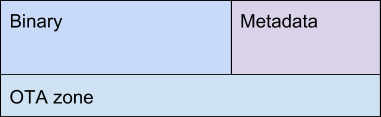
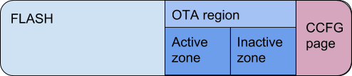
Following is the modified memory layout of the board flash:
In this new layout, the OTA region is introduced. This region contains 2 OTA zones:
Each OTA zone is composed of 2 parts, the binary part, as generated by the project build process and extracted from the project binary, and the metadata, containing information on how relocate and launch the binary part. Here’s a short outline of the metadata structure:
Field | Description | Type |
gen | OTA generation (increasing ordinal number) | uint32_t |
entrypoint | Offset of the entrypoint function in the zone’s binary region | void fn (void) |
size | Length of the binary region | size_t |
loads[MAX_LOADS] | Vector of relocations to be done from the binary region into the SRAM memory | struct ota_load |
done | Magic field to mark that region as valid | uint32_t |
The loads section specifies what parts of the binary should be copied to the board’s SRAM. These copies are needed to enable use of global variables. Each load element represents an ELF segment that should be loaded into the memory. Here’s the description of the ota_load struct:
Field | Description | Type |
dest | Copy destination address | uintptr_t |
offset | Offset of the copied data inside the binary region | size_t |
len | Number of bytes to copy | size_t |
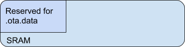
Additionally, to make sure the aforementioned loads do not interfere with the variables of the non-OTA code, we have to reserve part of the memory for the OTA programs. This way the compiler/linker will not allocate this memory to the OS/drivers when compiling the initial image.
On power-on, the OTA code check its zone for code it execute:
During the build of the firmware, the “.out ELF file”, we perform a post-processing step on the resulting ELF (.out file) and object files under ota_app dir.
The post-processing consists of:
The generated output (ota.json) is in .json format and it describes everything we need for performing OTA update using the blob (data) and metadata (offsets).
The background task of the simple peripheral (BLE) stack contains a callback that is triggered when GATT attributes are written. We reserved one of the GATT attributes (actually the 3rd one) to receive our “OTA update package” blob.
The “OTA update package” is transferred via a GATT client that reads the previously generated .json blob (see above) and communicates the entire blob (possibly in chunks) to the “BLE task” running on the board. Once the entire blob is transferred, the “inactive zone” is written with the new code and data and the board gets rebooted.
As we mentioned above, at boot time we determine that there’s a new app to run (via the “inactive zone” gen field), and we copy its contents to the active zone and boot into the new code.
Writing to a BLE attribute allows us to send a packet of a limited length. We tested the board and achieved 80-bytes as the recommended MTU for sending requests to the board. We implemented a simple request based protocol to allow transporting the whole blob of needed information to the board.
Each BLE packet contains of a header and the payload, with the header fields detailed below:
Name | Description | Type |
magic | Magic field, to identify OTA blob packets | uint32_t |
total_size | Total size of the blob in bytes | uint16_t |
cur_chunk | Index of the received blob chunk | uint8_t |
num_chunks | Total number of chunks in this update request | uint8_t |
chunk_len | Length of the current chunk | uint16_t |
Following this header is the payload of the OTA, which is the serialized data found in the JSON document generated during the extraction phase.
The searizalied data can then be read using the following struct:
Name | Description | Type |
entrypoint | Entrypoint for the metadata | uint16_t |
size | Size of the data stream | uint16_t |
loads[] | Array of ota_load structures | struct ota_load[] |
data | Binary stream of the OTA | uint8_t[] |
All the fields in the aforementioned headers are little endian.
During our development we came across TI’s implementation of over-the-air updates [2]. There are some similarities between our efforts, although, to our understanding, there are several key differences:
[1] Our GitHub repository: https://github.com/dimakuz/cc1350-ota
[2] Over the Air Download (OAD), Texas Instruments: http://dev.ti.com/tirex/content/simplelink_cc13x0_sdk_1_30_00_06/docs/blestack/html/cc1350/oad/oad.html