Portable GPS Tracker Project
Aviv Goll [avivgoll at gmail dot com]
Aviv Grafi [agrafi at gmail dot com]
Embedded Computing Course
Prof. Sivan Toledo Tel Aviv University Fall 2011
 |
Goal
The goal of the project is to build a portable GPS tracking device that can be used for tracking course while walking, running or driving.
The device will record the acquired coordinates in KML format to a SD/MMC based File System so the tracked course can be easily processed by GIS software such as Google Earth/Maps.
Due to portability requirements, the device is battery powered so power efficiency is required. The device will have idle/Low-Power mode to enable power consumption reduction mode.
Challenges
During the project we encountered several issues that were addressed.
- Custom board, SD Interface electrical design
The board we used lacked the SD interface. One of the first things we had to do is to focus on the SD/MMC electrical design and have it implemented as decribed in the relevant chapter. - Driving GPS controller
The GPS controller we used is pretty powerful. We had to learn its manual so we can understand how to control it and produce the necessary messages from it. - Handling GPS messages
Implementing an interrupt based UART driver to receive none synchronized messages from the GPS module. - Integrating File System
We wanted the application to produce PC readable text files on the SD card and for that we had to find and integrate a file system module. - Development and Debugging Environment
In order to debug out application parallel processes (GPS, file system, main) and the electrical design we created, we had to use a more advanced development environment including TI code composer IDE version 5.0, IAR WorkBench IDE version 5.20, TI JTag debugger and an Oscilloscope.
Use Case - Application Flow
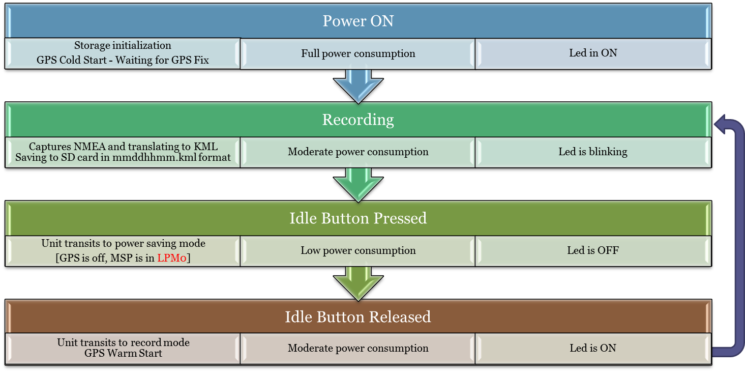
The device is meant to be powered at all times and the power consumption in idle mode was tuned to enable about a month of battery life. In reality our board was equipped with several additional peripherals such as an RF transmitter and voltage regulator which made the current consumption higher than expected – so we added a main power switch.
When the device is on - it’s in either a track mode or idle mode (selectable by
the Idle switch).
In track mode it is recording GPS coordinates to a file. The LED is constantly
ON until the 1st valid coordinate is acquired, then it's starting to blink
periodically for every valid acquired coordinate (pre-configured for every 5 seconds).
When switched back to idle mode using the idle button, it shuts the GPS power off, closes the file and transits to sleep mode until the next recording request. In this state the LED is constantly OFF.
Hardware
The hardware is proprietary board that was used for other unrelated project and was donated to our project and adapted to our needs by Virtual Extension. The main blocks are presented in the following diagram:
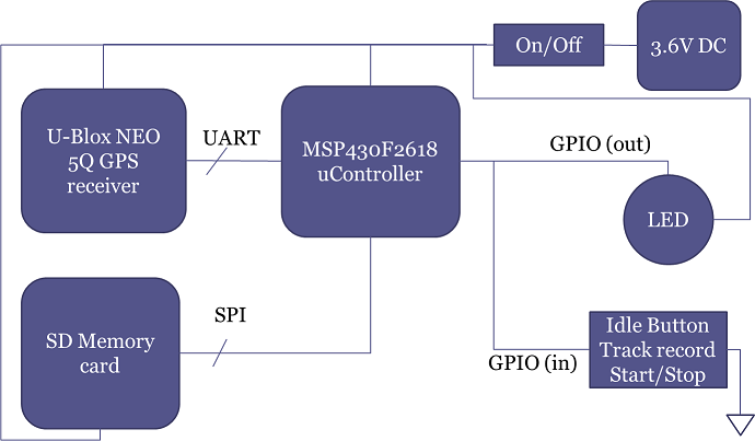
- Main processor - MSP430F2618 by Texas Instruments
- U-Blox NEO 5q GPS receiver
- SD/MMC card housing
- LED and button for user interface/control
- 3.6v DC power source battery based
- Main power switch
Software
The software blocks designed to drive the peripherals and to control application flow.
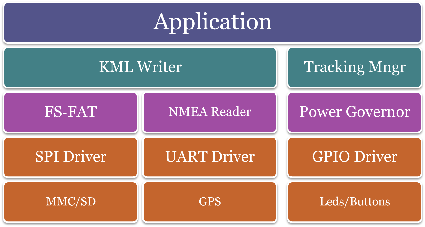
Drivers
During the development we had to implement several drivers:
- SPI Driver
Uses the SPI peripheral unit of the Micro-Controller – busy waiting for the HW to finish. - UART Driver
Uses the UART peripheral unit of the Micro-Controller – uses interrupts for none blocking calls and receiving messages while other processes are running. - GPIO Driver
Operates the LED and Idle/Record switch.
File System
The implemented File System is FatFS Version R0.09, which is a FAT16/32 implementation based on modular disk I/O routines.
The disk I/O routines we implemented are based on the SD/MMC init/read/write routines that were adapted from an example by Texas Instruments.
We also used the acquired GPS data to adjust the file system time stamps (so the creation/modification timestamp will be accurate).
NMEA Reader
NMEA is a standard GPS data protocol which is a default output from the GPS module we used.
We used some proprietary messages to setup which specific NMEA message we would like to receive. We tried several messages types such as GLL, GGA and RMC messages. Eventually, RMC was chosen for its detailed timing format.
The NMEA reader module is a string-parser which translates the received RMC message to a usable data structure. We defined two possible modes: Valid for GPS fixed based message and Invalid for no-fix GPS message.
- Sample NMEA Invalid line (no GPS fix):
“$GPRMC,,V,,,,,,,,,,N*53” - Sample NMEA Valid line (GPS fix): “$GPRMC,083559.00,A,4717.11437,N,00833.91522,E,0.004,77.52,091202,,,A*57”
- The data structure we defined holds the parsed data:
- Status: GPS_VALID
- Latitude: 4.72852401E+1
- Longitude: 8.56525325
- Time: 8:35:59
- Date: 9.12.2002
Deg = dd + ( mm.mmmm / 60.0 )
This module was written by us.
KML Writer
As an output format we chose KML files which are compatible with Google Earth PC software. We used a constant XML template (header + footer) that we filled with the parsed coordinates (Latitude and Longitude) received from the NMEA reader module.
The file name is the time of the first fix in MMDDHHmm.KML format. Samples can be found here.
- MM – Month
- DD – Day of the month
- HH – Hour of the day (24 hours format)
- mm – minutes of the hour
Tests and Samples
- GPS wait-for-fix timing
- 1-2 minutes on initial boot
- Less than 30 seconds for re-fix after return from idle mode
- Power Consumption:
- Idle/Lowpower 4mA
- GPS is off
- MSP is in LPM0
- Recording 110mA
- GPS is on
- MSP is on
- Idle/Lowpower 4mA
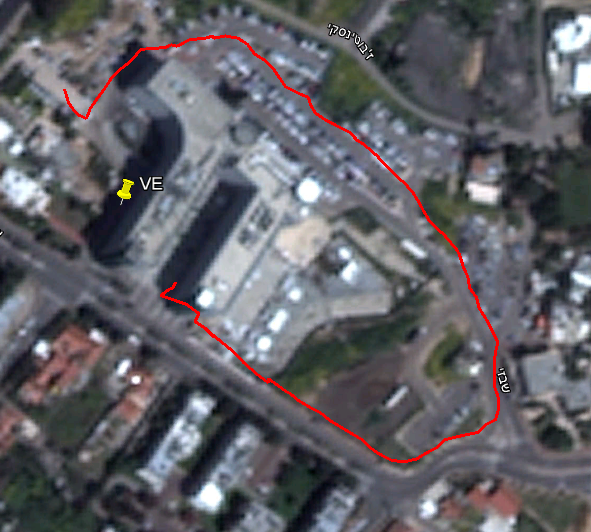
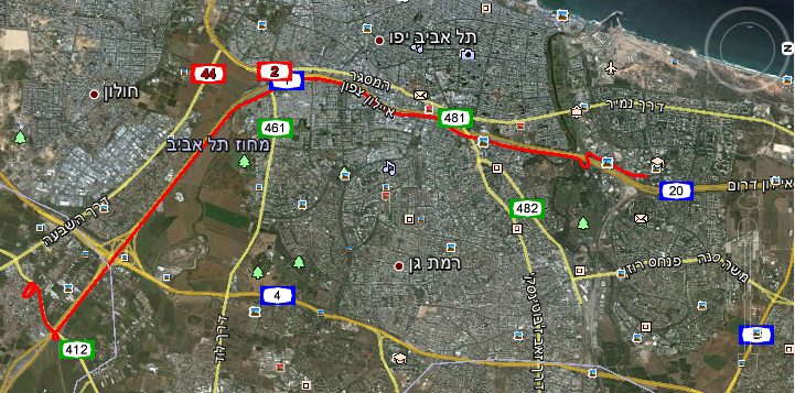
- Output samples (KML files can be opened by Google Earth to produce these pictures):
- Sample Track – Walking around the building –
03310947.KML
- Sample Track – Walking around the building –
03310947.KML
- Sample Track – Driving to the university (Board placed on the dashboard) – 04020757.KML
SD-SPI Schemes
As mentioned earlier, we designed the SD-SPI interface including the electrical
scheme:
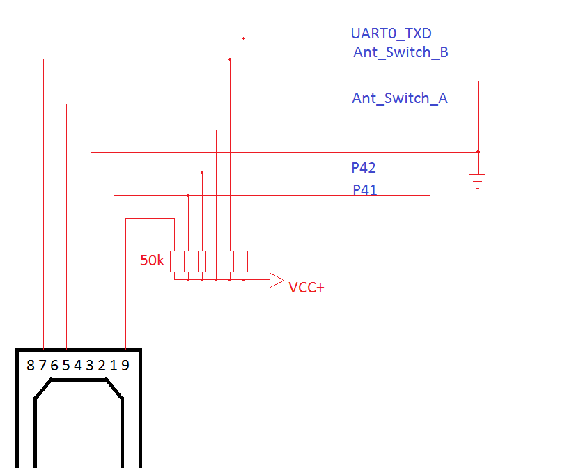
The line names are compatible with the board
electrical scheme we got.
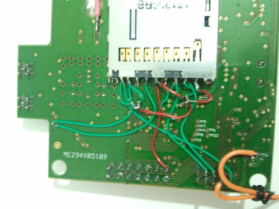
This wiring was implemented by a professional technician and it looks in reality
like that:
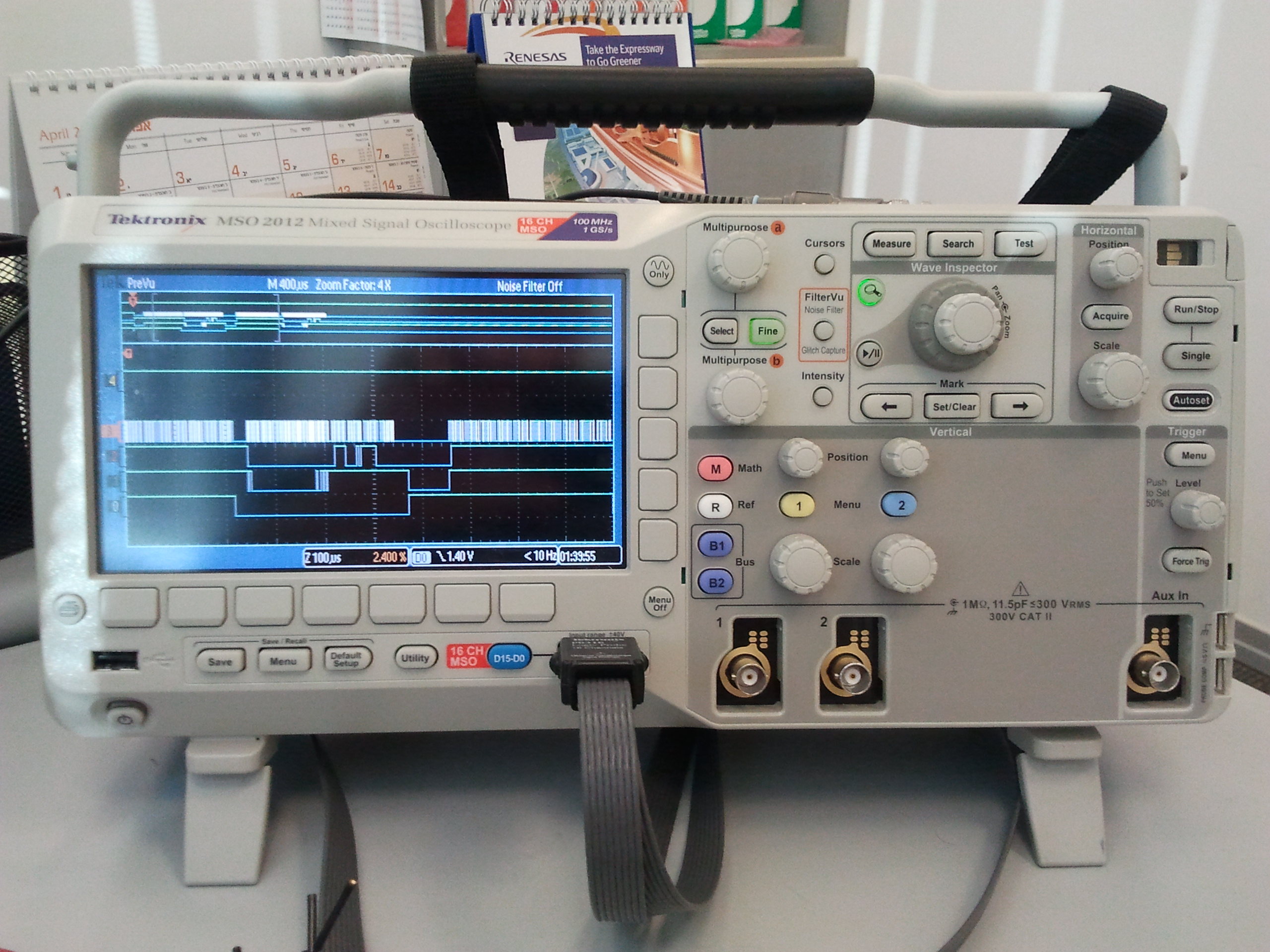
As part of the development we integrated the SPI layer based on TI source code examples. We had several integration bugs, mainly on SPI interface and initialization routines that we had to solve by carefully following the wires states using Oscilloscope that connected to pins 1, 2, 5 and 7 of the SD/MMC card.
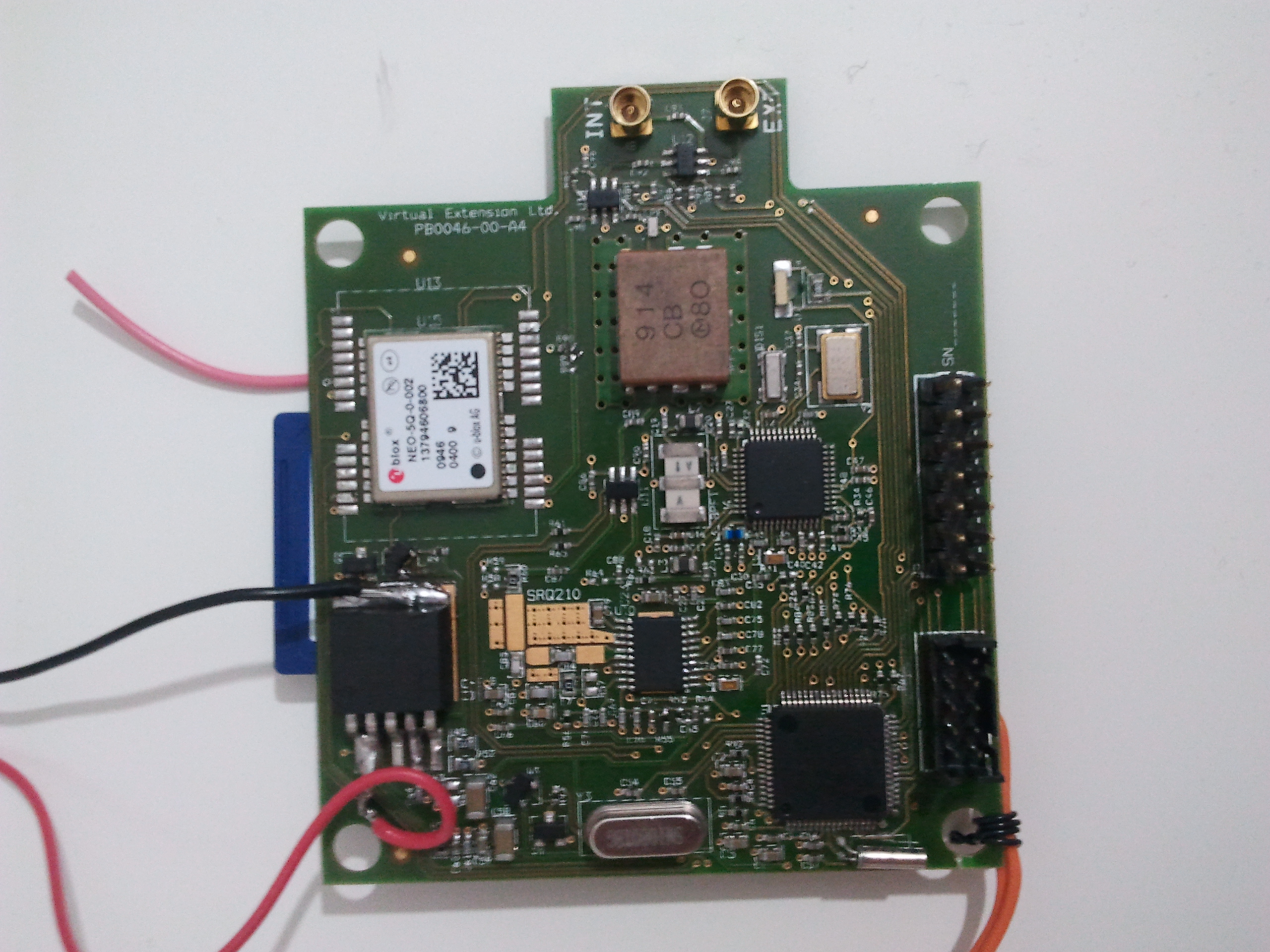
Pictures of the board:
Side 1: The micro-controller, GPS module and LED.
Side 2: The SD House, GPS antenna (pink wire) and custom SD/MMC SPI wiring..

Entire device: The board, battery and 2 switches (orange wires are connected to the idle switch)
Front
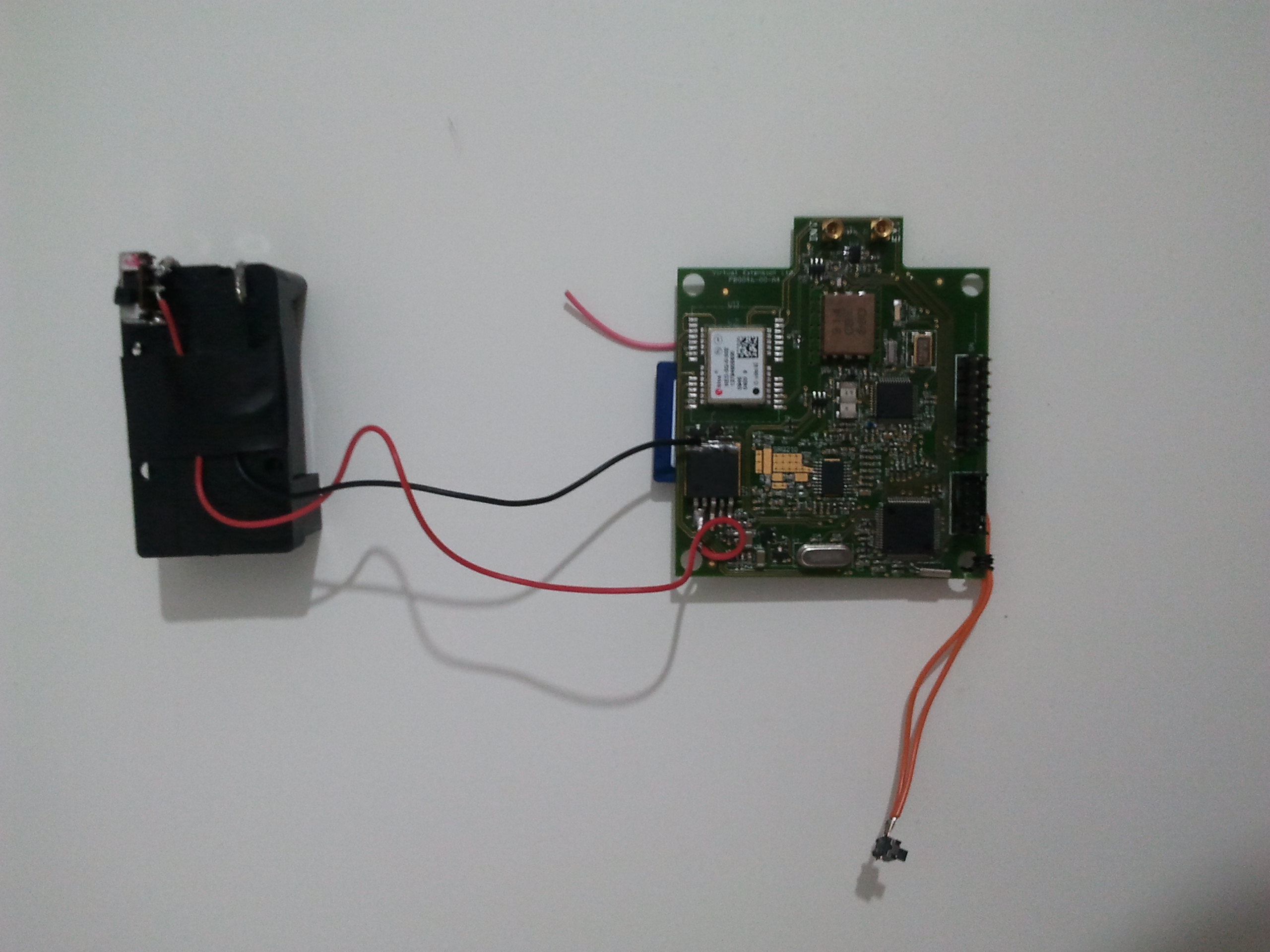
Back

Future Possible Enhancements and Ideas
- Remove power consuming voltage regulator.
- Connect board to network assisted GPS.
- Attach Wi-Fi device and transmit GPS samples directly to nearby server.
- Reduce MSP430 power consumption by:
- Turning the clocks off.
- Using LPM 3/4.
- Reducing GPS module power consumption and/or fix time
- Switching it to power save mode.
- Using GPS-Stop command instead of cutting its power completely – which is what’s done today.
- Application
- Software interrupts on GPS messages instead of polling – which is what’s done today.
- Use a different (more suitable) battery.
Source Code
The source code is hosted on Google Code repository and can be obtained by visiting the project page. Project presentation can be found here